
For the past few years I have been building motor controllers with generally good success. In the past year, for the first time I have delved into making custom motors as well. For the project mentioned in this article, I used the laminations from an air conditioner, but for my latest motor (the 250lb RIPperoni motor, to be discussed in a future blog post) I designed a fully custom rotor in FEMM, and had the resulting lamination/magnet combo manufactured overseas. This is a lot of effort, but the performance achievable is far superior to anything else on the market. A question I am always I asked: Why go though all the effort of building your own motor/controller setup?
The answer is a bit complex, not really one answer but rather a combo of features which make the final project vastly superior to off-the-shelf options.
- The ability to support IPMs. IPMs have the constant-power behavior ideal for driving EVs and spinning up large masses. High speed operation is possible because of field weakening, which means you can gear the motor a lot better. In the context of EVs, you can gear for max efficiency at 25mph but then have the ability to do 50 mph, or in the context of battlebots you can gear for 100mph to spin up quick but then have the ability to hit 250. The high motor inductance also means you can switch very slowly, reduced switching losses and improving efficiency.
- Mechanical robustness. The IPM geometry means that the magnets cannot fall off, and even if they do crack they won’t jam up the motor. The controller can also be designed to fit directly onto the motor, mitigating both the phase wire problems and encoder problems, which is a big deal.
- Full control of the software stack. I can tune the software for whatever behavior is desirable. I can even have advanced features like “motor does not make clunking noises at low speeds” which apparently is a feature not all motor drives have.
May catch on fire but thats besides the point
So what type of motor to build?
After using pancake inrunners for both small and Big Ripperoni, I am 100% sold on inrunners. Outrunners always need some sort of cage around them to avoid ingesting other robot parts into the outrunner, so the total volume occupied the weapon motor setup ends up being large. Inrunners also are better from a thermal perspective. Additionally, many teams end up building back bearing supports for their outrunners, basically turning the outrunner back into an inrunner. Inrunners reign supreme.
So, inrunners. Most inrunners are pretty long and thin, termed “hotdog” motors. The motor spins so fast that it needs at least a 6:1 planetary to do anything useful in robot duty. The other side of this is termed “Pancake” motors. Pancake inrunners are slightly more rare in the hobby market than pancake outrunners, but they are common in the automotive area (see most alternators and the classic prius motors). Pancake motors produce more torque at a lower speed compared to their hotdog counterparts. Pancake motors also have more end-turns compared to their hotdog motor counterparts, and therefore theoretically have higher resistance and lower efficiency. However, the reduced efficiency is made up for by the fact that pancake motors usually do not require gearboxes to output a reasonable torque/speed, which vastly increases general usefulness as well as reducing weight, and probably the gearbox losses are roughly equivalent to the end-turn losses anyways. Additionally, a pancake motor also has a larger backplate area per unit motor, which serves as a convenient place to mount an inverter. The whole pancake inrunner motor plus back mounted inverter can make a pretty good motor module. So: Pancake inrunners IMO is optimal for motor goodness.
Time to make one. This is from a while ago, but it was a pretty cool project. Anna’s 30lb Riperoni needed a motor, and the obvious choice was a small IPM for the big beans. A full Prius air conditioner motor is a bit much for a 30lber, as well as needing way too many volts. Something fun I’ve always wanted to try was to take a stator stack, split it in half, and rewind the stack. This was a perfect excuse to do so. The half-stack motor is a very pancakey motor, which is what we are looking for. Time to build!
Step 1 was cutting off the windings and splitting the stator. This was easier than expected. The original stack is about 30 mm tall, so the resultant half-stack stator was about 15mm. I bought some Nomex paper and made little slot liners. These inserted quite nicely. I pre-formed the coils on a 3D-printed form and then inserted them into the motor. I don’t remember exactly what Kv I wound for, but it was roughly ’48V gives usable RPM.’ Let the winding commence.

Winding this stack was relatively easy as the stack was pretty short. Stuffing the windings in gets harder as the stator gets longer. Hypothetically, it is possible to stack prius stators instead of splitting them, which would be very amusing, and lead to a very long motor. Winding this stator took about a week. I did look into doing a concentrated winding, but found it unsatisfactory and so, as expected, the ratio of end turn to motor was very large. Every time I wind one of these motors I swear I will never do it again, but then somehow I do. The ratio of motor to end turn was pretty bad on this motor, but that’s just what you get on a pancake motor. I was able to pack in a lot of turns on this motor, so the fill factor in the slots was very high.

I wrapped the end turns of the stator in kapton tape so that they would not be damaged during insertion into the aluminum housing. We got some housings machined from SunPe. The housing turned out pretty well. Here is the finished stator next to the housing.

Next up: making the rotor.
I pressed the stack off the shaft and drilled out the rivets.

The stack came apart and I was able to pull out the magnets. How to make half-size magnets? Simply break the magnets in half. The magnets snapped in half with minimal effort after being scored. I did this in my horizontal mill vise, which has very sharp edges. The magnets were a little softer than I expected. I’m not really sure if they were actually neodymium, but ‘good enuf.’

The stack was reassembled onto a Misumi shaft, and the magnets were inserted. I turned two snap ring grooves and also relieved some of the shoulder material for weight reduction.

At this point in the project, the competition was two days away and the motor was nowhere close to being done. As usual I managed to lose the keystock which keys the rotor laminations onto the shaft. Rather than wasting even more time looking through the eternal wasteland of my living room, another solution was devised with extreme haste:

The weldblob was then milled into shape on the index mill. 50% of the people that saw this thought it was the stupidest thing they had ever seen, but the other 50% was impressed by my perceived ingenuity. Hey it worked, pretty funny.

The rotor, mostly assembled, showing the magnets. An endcap covers this to prevent the magnets from falling out the end.

The stator and rotor came together in a nice weight-optimized housing we got from SunPe. Motor almost done!

MOTOR ASSEMBLED!

Next up: Controller.
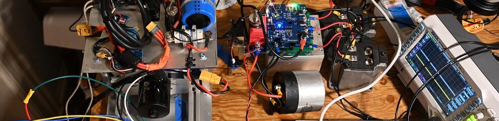
Here is the controller. This controller came out pretty well. The only major error was that I screwed up the inductor footprint so I needed to bodge that a bit, but otherwise it was great.

I forgot to take pictures of the motor unit, but it was pretty ugly. Most notably, I forgot to include any provisions whatsoever for a controller shroud, so the controller was packed with paper towels and shielded with probably 1/4″ thickness of duct tape and electrical tape.
Finally: installation into robot. Anna did an excellent job designing the rest of this robot. Tony also did an excellent job with decals, which turned the robot into the star of the show.

Here are some of our fights:
30lb Riperoni was pretty good! Couldn’t really turn but it somehow managed to do alright. What if, somehow, by some miracle, someone managed to put a countergyro on a robot…
