Ain’t nuthin better than getting a hunk o’ junk on Ebay and turning it on, and even better: making it do something useful.
The original plan for the Big Dyno was to use a Prius inductor– based buck converter. However, the good ole Prius inductor proved just barely not quite up for the task, with a saturation current of around 175A. Practically, this means it is only good for about 150A of boosting, and I was really hoping for the full 200A (although I will use that quite rarely, it is a nice-to-have for sure). I was able to find some specs in this ORNL report about the booster in the Camry. It lists the Camry boost converter power as 30 kW, or 125A input at 240V. This is a sizable increase from the Prius’s 20 kW, or 100A at 200V.

Time to acquire the cheapest one I could find on Ebay, which had a marginally damaged connector.

Top guts:

After the capacitor proved impossible to remove, I realized there were two busbar bolts hiding behind a small cover.

The bottom guts. The bottom houses a brain board which sits on top of the double inverter unit, which has its own board. My guess is that the top board manages the control of both motors as well as the boost converter. Both boards are full of weird Japanese chips.

The top board removed, exposing the double 3-phase inverter brick. Most interesting are the six square rectangular objects, which sit proud of the board by 1-2mm. I originally thought these objects may be ferrite sheets covering planar magnetic power converters, however the black objects are are nonmagnetic so my guess is that they are just more standard power converters.

Next up: splitting the modules. The upper part containing the boost converter is completely self-contained, as well as the lower part which houses inverter module. The hot sides of both part’s power devices face a common water block. Very noticeable in this module is the vast increase in space efficiency and integration compared to the Prius power module, which comparatively resembles a bunch of components thrown into an enclosure haphazardly connected with busbar. There is almost no wasted space in this module whatsoever. All in all, the design here is quite remarkable, especially considering it was probably designed in 2005. The water block inside this module is also quite cool, with strange-shaped curves and even ribbed fins under certain areas (possibly to increase power dissipation?).

The booster module.

The original plan was to just straight-up bandsaw the inductor out of this thing, because as indicated by the ORNL report, it is potted in. However, after looking at the booster, I just couldn’t bring myself to do it, as the space efficiency of this unit can’t be beat. It even comes already mounted to a water block, busbar-ed into a perfectly matched brick with integrated gate drivers, and even has some capacitors as well (0.9 uF straight across the brick plus 500uF on the output of the inductor).
So, change of plans- let’s try to turn this thing on. Rather than use it for parts in the Big Dyno, I plan to just shove the whole unit in, as a self-contained booster blob.
Unfortunately, getting the brick to switch proved very challenging. Somehow, by some miracle the wiring diagram for the internals of the Prius inverter can be found online, which is insane as a 600-800V inverter really shouldn’t be serviced by Joe’s auto repair. Unfortunately, Toyota was not kind enough to release the internal wiring diagrams for this brick (the external ones can be found, but have no information relating to the internal booster wiring, which never ventures outside this box). I tried for a while to send random input voltages into the wiring harness on the booster, but didn’t try too hard as I didn’t want to damage anything. That obviously didn’t work, so I probed one level deeper. The booster is made of a stack of two boards. A gate-drive board solders onto the brick, and then a power supply board gets soldered on top. I really didn’t want to de-solder the power supply board from the stack.

Eventually, I found something useful: there are a total of twelve pins which connect the power supply board to the gate drive board underneath. I found two of these pins were wired to identical SOT89-looking transistors through 75 ohm resistors, and the other end of the transistors connected to ground. Sounds like two open-collector inputs to me………

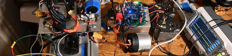
Time to desolder those 75 ohm resistors, and insert some open-collector opto-isolators instead, which then got wired to the good-ole F303K8. The isolators aren’t strictly necessary here as the gate drive board is already isolated, although an extra layer of isolation never hurts (so long as the propagation delays don’t become sizable!). I had the isolators on my desk and I’m not sure where my stash of BJTs went, so isolators it was….

Against all odds, this actually just straight-up worked. Time to get boosted.

Unfortunately, because this booster is so huge, it demanded that I move the electronics pile to the bottom of the dyno. My dreams of a dyno with easily-serviceable electronics are moot.

More to come….