
Over the past week I built a lil 1lb melty for a low-key local plastic ant competition. I have tried several times before to build melty brain robots, but never had the greatest luck. Now armed with many more years of breaking stuff robot experience, it was time to try again.
I’ve always found the biggest problem with melty brain robots to be keeping the rapidly spinning robot synchronized to the rest of the world. Most melty brains have used an IMU sensing centrifugal acceleration to calculate velocity, and then integrated velocity to get position. This works ok, but because there is no global world reference the integrator will drift and the driver will have to be pretty on top of the yaw signal, and after every hit the robot ends up in a random direction. Many other solutions have been tried to improve upon the accelerometer solution, with some success: IR beacons, wheel RPM sensing, and even compasses. The IR beacon method seemed to be the most successful of these, and is used by the well-known 3lb melty Project Liftoff.
For my melty brain, I chose to try an novel technique for position sensing: using a rotating coil magnetometer to sense the earth’s magnetic field, and thus have a global heading reference. A coil spinning in a magnetic field will develop a sinusoidal voltage across it, so in this case, if we just mount a coil to our rapidly spinning robot and set it anywhere on earth except the north or south pole, we can get a heading signal. It turns out I am not the first to think of this, but as far as I know I am the first to actually put it on a spinning, drivable robot. The key here was not to use one coil, but rather two offset at 90 degrees, and to just use the atan2 function to directly get angular position.
Here’s a video of driving around my tiny test box. The heading is rock-solid and the translation was great too!
One question worth answering: Why not just use a compass IC?
Well, simply put… compasses are terrible. One bad trace under the 2mm square IC and your measurement is garbage. My thought was that, simply by nature of the coils being physically 1000x larger than a compass IC, the coils will pick up more signal. It turns out that big coils will also pick up more magnetic flux from unintended sources, but there’s a difference- unintended signals can be characterized and filtered out, whereas garbage noise is harder. For example, any brushless motor emits magnetic noise, but it isn’t really noise: the motor commutates much faster than the robot spins, so we can filter that high frequency noise out. Also, all of the standard compass ICs don’t generally run fast enough to keep up with the rapidly spinning robot. It’s probably worth trying a compass for a future bot, but I chose to try the coils for this one.
The Technical Bits…
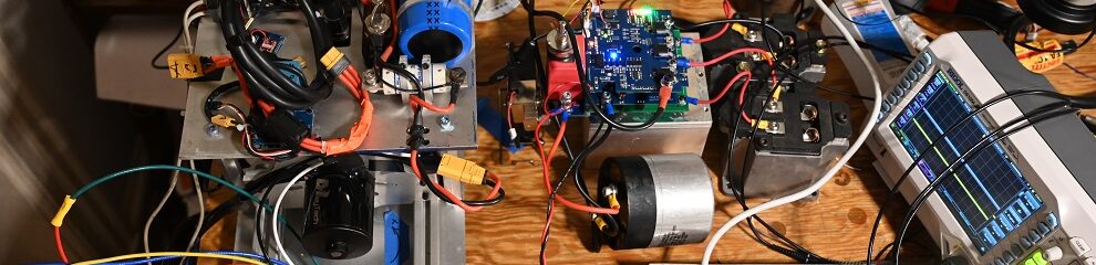
It turns out that the voltage across the coil is quite small. Even for a coil rotating at 1000 RPM, even with 1000 turns the signal is less than a millivolt. In order to get this to be something reasonable, the signal has to be amplified by about 1000X. I laid out a little PCB to do this. The PCB has an STM32G431 and a quad low-noise op amp on it. Two of the op-amp channels were used for amplifying the two coil signals, and the other two channels were saved for future photodiode use. The PCB also had a high current switch for driving LEDs and a connector for my data logger as well.

I printed out a melty robot shell. In keeping with my team’s tradition, the robot was to be named Deep Dish. The PCB has outputs for two motors, but I only had weight for one, so one motor it was…

I wound the coils on my lathe. I 3-D printed out little bobbins and fed the wire on as the lathe spun. I have no idea how turns ended up on the coil, but it was 30AWG wire, so probably at close to 1000. Once the bobbin looked full, I potted the coil in hot glue, “to ensure robustness.“

The coils (and the rest of the electronics crap) “mounted” (ie just shoved in) inside the robot. The key here was to mount the coils as far as possible from the motor, which is the largest source of magnetic noise on the robot. Note that the coils are at 90 degrees- this gives the sine and cosine signal we need.

Jumping a head a bit, here’s the gist of how this works: the two coils sense the magnetic flux, and convert the changing magnetic flux into a voltage. The two voltages are a sine and cosine, so we can feed that into the atan2 function to get a position.

Next Up: The Bits and Bytes
Time for some programming. I wrote some C code which drove most of the important functions.
The setup for this code consisted of significant direct register bashing, maybe I will put it on Github one day once it is fit for human eyes. The setup code really just set up the ADCs into maximum resolution mode and turned on the PWM signals.
// ============= sample flux detectors ==============

sensor_data.flux_1 = sensor_data.ADC2_array[0] - sensor_data.flux_1_offset;
sensor_data.flux_2 = sensor_data.ADC2_array[1] - sensor_data.flux_2_offset;

sensor_data.flux_1_offset = (sensor_data.flux_1_offset*0.99937f) + (sensor_data.ADC2_array[0]*(1.0f - 0.99937f));
sensor_data.flux_2_offset = (sensor_data.flux_2_offset*0.99937f) + (sensor_data.ADC2_array[1]*(1.0f - 0.99937f));


sensor_data.flux_1_buf[sensor_data.flux_1_buf_index] = sensor_data.flux_1;
sensor_data.flux_1_buf_index++; if (sensor_data.flux_1_buf_index >= 10 ) { sensor_data.flux_1_buf_index = 0;}
sensor_data.flux_2_buf[sensor_data.flux_2_buf_index] = sensor_data.flux_2;
sensor_data.flux_2_buf_index++; if (sensor_data.flux_2_buf_index >= 10 ) { sensor_data.flux_2_buf_index = 0;}

sensor_data.flux_1_filt = 0.0f;
sensor_data.flux_2_filt = 0.0f;
for (int i = 0; i<10; i++){
	sensor_data.flux_1_filt+=sensor_data.flux_1_buf[i];
	sensor_data.flux_2_filt+=sensor_data.flux_2_buf[i];
}


// ============ read radio commands ==============

if (TIM8->CNT > 50000) { // consider input dead
	command.transX = 0.0f;
	command.transY = 0.0f;
} else if ((TIM8->CNT > 3000) && (DMA1_Channel1->CNDTR < 7)) { // copy the signal

	DMA1_Channel1->CCR &= ~DMA_CCR_EN;
	DMA1_Channel1->CCR &= ~DMA_CCR_EN;
	DMA1_Channel1->CNDTR = 10;
	DMA1_Channel1->CCR |= DMA_CCR_EN;

	command.transX = ((command.RCPWM_channel_buffer[1] - 1531)/490.0f);
	constrain(&(command.transX), -1.0f, 1.0f);
	command.transY = ((command.RCPWM_channel_buffer[2] - 1531)/490.0f);
	constrain(&(command.transY), -1.0f, 1.0f);
	command.thr = ((command.RCPWM_channel_buffer[3] - 1015)/990.0f);
	constrain(&(command.thr), 0.0f, 1.0f);
	command.yaw = ((command.RCPWM_channel_buffer[4] - 1531)/490.0f);
	constrain(&(command.yaw), -1.0f, 1.0f);

	if (command.RCPWM_channel_buffer[5] > 1500) {mainvars.motor_reverse = 1;}
	else {mainvars.motor_reverse = 0;}
}

if (fabsf(command.yaw) > 0.07f) { command.yaw_integrator += command.yaw/5000.0f*6.28f; }
if (command.yaw_integrator > 3.14159f) { command.yaw_integrator -= 6.28f;}
if (command.yaw_integrator < -3.14159f) { command.yaw_integrator += 6.28f;}


// =========== calculate position =================
float pos_raw = 0.0f;

pos_raw = atan2f( -sensor_data.flux_2_filt, sensor_data.flux_1_filt ) + command.yaw_integrator;
if (pos_raw > 6.28f) { pos_raw -= 6.28f;}
if (pos_raw < 0.0f) { pos_raw += 6.28f;}
if (pos_raw > 6.28f) { pos_raw -= 6.28f;}
if (pos_raw < 0.0f) { pos_raw += 6.28f;}

// reset filter if throttle is zero
if (mainvars.M1cmd == 0.0f) {
	heading_L2F.X = pos_raw;
	heading_L2F.V = 0.0f;
} else {

	// run pos filter
	Wrapping_Type2_Update(&heading_L2F, pos_raw);
}


// ============== write heading LED =======================
if (mainvars.M1cmd != 0.0f) {
	if ((heading_L2F.X > 1.0f) && (heading_L2F.X < 5.28f)) {
		HAL_GPIO_WritePin(HEADING_LED_GPIO_Port, HEADING_LED_Pin, GPIO_PIN_RESET);
		HAL_GPIO_WritePin(HEADING_LED2_GPIO_Port, HEADING_LED2_Pin, GPIO_PIN_RESET);
	} else {
		HAL_GPIO_WritePin(HEADING_LED_GPIO_Port, HEADING_LED_Pin, GPIO_PIN_SET);
		HAL_GPIO_WritePin(HEADING_LED2_GPIO_Port, HEADING_LED2_Pin, GPIO_PIN_SET);
	}
}

// ============= map commands ================

mainvars.transX = command.transX;
mainvars.transY = command.transY;

mainvars.spin_torque = command.thr;

if (command.thr > 0.1f) {mainvars.motor_enable = 1;} else {mainvars.motor_enable = 0;}

// ============ write motor commands ============
float phase_adv = 0.8f;

if (mainvars.motor_reverse) {
	phase_adv = -phase_adv;
	mainvars.spin_torque = -mainvars.spin_torque;
}

if (mainvars.motor_enable) {
	limit_norm(&(mainvars.transX), &(mainvars.transY), 1.0f);

	float sin_temp; float cos_temp;
	CordicSinCos(heading_L2F.X + phase_adv, &cos_temp, &sin_temp);

	mainvars.M1cmd =  cos_temp*mainvars.transX + sin_temp*mainvars.transY + mainvars.spin_torque;
	//mainvars.M2cmd = -cos_temp*mainvars.trans_X + sin_temp*mainvars.trans_Y;

	// motor PWM values are 10 to 20 microseconds, 15 microseconds = 0 torque
	constrain(&(mainvars.M1cmd), -1.0f, 1.0f);
} else {
	mainvars.M1cmd = 0.0f;
}
TIM1->CCR1 = (15.0f + 5.0f*mainvars.M1cmd)*170.0f;
Here’s the explanation of this code:
- The program starts by reading the ADCs. The ADC values aren’t scaled at all- the beauty of the arctan is that we only care about the ratio between the two.
- Next up, we subtract a 0.5Hz low-pass filtered value of the ADC from the most recent ADC value. This high-passes the signals. High-passing at 0.5Hz get’s rid of DC offsets caused by ADC drift, and we are measuring only AC signals on the order of 20Hz to 200Hz, so high-passing doesn’t cause problems.
- We then FIR filter the most recent 10 values of the ADC. This reduces the noise a bit, and effectively forms a low-pass filter with cutoff 500hz. Therefore, the filtered signals are band-passed between 0.5Hz and 500hz. I probably could have strengthened these filters, but wanted to start with less filtering to just look at the data. The FIR filter actually multiplies the values by 10, but again, we only care about the magnitude of the two signals relative to each other so this doesn’t matter.
- We read the RC receiver inputs with the DMA. DMA FTW! The only interesting thing here is the yaw value. The position returned by the flux values will always point true north, and it’s annoying to hold your transmitter stick over to the side continuously to always get the robot to point west. So, we integrate the RC input value to get the yaw signal, which will be applied as an offset to the filter.
- Next up: running the atan2! We feed the flux signals into the atan2() function. This function returns a value from -pi to pi, so we wrap it to be between 0 and 2pi, which is what the type 2 loop filter will take.
- Next up: take the raw position and feed it into a type 2 tracking loop. Type 2 tracking loops are really excellent, smoothing raw position data extremely well (keep reading to see!). The best description I’ve found on type 2 tracking loops is the AD2S1205 datasheet. Basically, a type two tracking loop is a double integrator with a lead compensator for stability, the lead adding positive phase to the otherwise -180 degree phase of the double integrators. These integrators need to be reset when the robot isn’t spinning to make sure they don’t wind up, so I do whenever the motor command is zero.
- Using the filtered heading, we write the heading LED. The heading LED basically tells you instantly whether the robot is working or not.
- Finally, we write the motor commands. This filtered heading is fed into the sine/cosine which modulates the motor commands. Its that simple!!
Testing the bot
To my IMMENSE surprise, this whole setup of coils, op amps, and digital filters more or less worked on the first spin-up. Which was lucky really, as this was the night before the competition and I didn’t have a lot of time for debugging. You can see the throttle value increase, the raw and filtered positions converge to a trapezoid wave, which is exactly as desired- the position is an increasing value from 0 to 2*pi, where is rolls back to zero. Here’s a plot of the data log:
For the next spinup I fixed a few sign errors and tuned the L2 filter better. Here are some plots.
First is the spinup. More or less the same performance as before but significantly better tracking.

Zoomed in. The raw position is ripply as expected, but the L2 filter smooths out all the noise. It is interesting to see how non-sinusoidal the flux measurements are. They are definitely periodic, but have significantly more high frequency content. This causes the raw atan2 output to have a predictable notch, where the robot thinks its rotating backwards for a millisecond. The filter does a good job of rejecting this noise.

Here’s a plot of starting the filter. I constrained the filter to be equal to the atan2 raw position if the motor command was zero. So, quickly dropping the throttle to zero would reset the filter. Here is a plot of doing that. The velocity starts at zero and the filter “misses” a robot revolution. But eventually, the filter catches up.

Interestingly though, things did not always go to plan. This filter is a double integrator, and integrator windup is a thing (more on this later..). If the filter got slightly wrong information on startup, the integrators would wind up real fast and just give a totally wrong position. Here, the fluxes are zero, so the robot isn’t spinning, and the raw atan2 position reflects that. However, the velocity integrator thought it saw a rapidly spinning robot, so it spooled up despite the fact that the robot isn’t spinning at all.

This behavior also would not fix itself…

But eventually as the robot “caught up” to the filter things would resolve themselves. I think the actual answer here is to have an accelerometer as well as this filter, and constrain the velocity to be within ~30% of what the accelerometer thinks it is.

One final interesting note is what happens when you drive near something steel. I noticed weird lumps in my data logs occasionally and I believe these were times when I drove by my toolbox, which I was using as a wall of the arena and was full of steel tools. The filter just does its best to keep up with the extreme noise and crap, and it does so OK.

Anyways, with all that working, I did get to do some pretty cool driving. I’m happy to say the melty worked great driving around my test box. See the video at the top- the heading is rock solid and the translation was quick and smooth.
With all that working well enough, I packed up all my stuff in a big box, and got what sleep I could before the competition.
Competition Day
They say no plan survives contact with the enemy, and today’s comp would be no exception. Deep dish ended up going 0 and 2, which was a bit of a downer, but still, I was happy it worked at all. Here are the fights.
For the first fight I was up against Angel’s vert. The robots hit each other and then deep dish got stuck. Why did deep dish get stuck? Friggin integrator windup. It turns out that the motor controller used the same Type 2 filter as the brain of the robot, to smooth the data from the hall sensors. And so, during a hard hit, if the motor stopped fast enough, the filter would just keep going, and cause the motor to seize. I had realized this was a problem at 11pm the night before, but fixing it required disassembling the whole robot to reprogram the motor controller. I was obviously too lazy to fix this and therefore I lost. Ripperoni Rigatoni!
Feeling rather dumb I finally did dissemble the robot and reprogram the motor controller, adding code which reset the integrator in the motor controller.
2nd fight: Brandon’s horizontal, A Aant!!
Brandon drove great in this match, putting me in the melty corner and staying on me the whole time. Early in the fight he hit part of the wheel, which made the wheel into a D shape. The motor still had enough torque to rotate, but not enough to spin the robot. Eventually Brandon managed to remove the rest of the wheel and Deep Dish was done.
So, 0 for 2. Still, the robot accomplished its main objective of showing that the rotating coil magnetometer can work. So, I’ll probably build a bigger robot for Motorama or something. We’ll see if this happens.
I replaced the exploded wheel, and did get a chance to drive around the box a bit. When there were no other robots in the box, it did work, but not as well as it did at home. As soon as I spun up, the robot would shoot off in a random direction and hit the wall. I mostly blame the box for this, as the box floor was super torn up, and so the wheels would hit holes and cause the robot to drive badly. However, this is basically every battlebox ever, so in order to be competitive, the melty probably has to do something more advanced, like have sonar to avoid walls or something like that. We’ll see what I end up doing in the future.
Lessons Learned
The Good:
- The motor and motor controller worked great. The motor could do burnouts.
- The magnetic tracking worked pretty well, although not as well as it did at home.
- The heading LEDs were good. They were very bright when the robot was stopped, but they needed this brightness when the robot was spinning.
- The neoprene rubber wheel worked great an was easily replaceable.
The “Needs Improvement”:
- Use two wheels. Deep Dish got stuck in the corner a bunch, which isn’t as much of a problem for 2-wheeled meltys.
- Use locking connectors. The RCPWM connector for the motor controller would come unplugged occasionally. This obviously is bad.
- Do something about the ping-ponging. IR wall detection? Sonar? TBD.
We’ll see what the future brings on this project…