
The land of motor ratings is pretty dubious. All too often, people say, “yes, this motor has a stall torque of 11.8 Nm and a no-load speed of 16krpm- therefore this motor produces TWENTY THOUSAND WATTS.” Alright then…
But did you actually measure that? How do we even measure power of a motor in the first place? What even is power? Let’s get into the physics…
An electric motor is a device which converts electrical power into mechanical power, usually through a magnetic field. The same device is also a generator, when the flow of power is reversed and the mechanical power is converted back into electrical power. This is also referred to as “regeneratively braking.”

Most of the time, the power we care about is the mechanical shaft output power produced by the motor. Torque is measured in newton meters and speed in measured in radians per second, so when multiplied the answer comes out in watts.
Electrical power is also useful to know. Volts is measured in volts and amps is measured in amps, and when multiplied the resulting answer comes out in watts.
These equations cannot simply be set equal to each other to find the remaining variable, because there will always be losses in the system. These losses are dissipated as heat. Due to conservation of energy, the full equation is:
Efficiency for motoring operation is mechanical power divided by electrical power. A normal brushless motor might reach a peak efficiency around 90%, but will be less efficient across most of its operating range.
Motors are not very efficient at some operating ranges, most notably at low speed and high torque setpoints. 1 kW could be coming out of the battery, but if the motor is stalled, the speed will be zero, and therefore the efficiency will also be zero- this means the motor will be generating 1 kW of heat and will quickly catch on fire. Anyways- the four variables to keep track of here are: torque, speed, volts, and amps. In order to characterize a motor, we must measure these four parameters with high accuracy.
One final note is worth mentioning before we enter the practical realm. As most motors these days are brushless, we have to measure not only the efficiency of the motor, but of the inverter as well. My opinion on this matter is that measuring either one individually is almost completely useless. The efficiency of a brushless motor completely depends on how well the inverter drives it. For example, lowering the switching frequency of the inverter would reduce inverter losses, therefore increasing inverter efficiency. However, this will reduce motor efficiency as ripple current increases. Therefore, I always think of the motor and inverter as a system which is a mated pair.

Moving on to the practical stuff.
It’s generally not too hard to measure electrical power, but measuring mechanical power is a bit trickier as we have to accurately measure the torque produced by the motor. Additionally, we need create a load for the motor to apply torque against. The most intuitive and vaguely real-world situation I’ve seen is to test with an inertial load. This is what a lot of the car dynos do: the vehicle is rolled onto a set of heavy rollers, and load is provided my the roller’s own inertia.
Just measure the speed of the roller, differentiate, multiply by the roller MOI, and you get the torque. The measurement will be noisy, but good enough for ballpark testing. I’ve seen a lot of Battlebot teams do this by cutting out massive steel disks and spinning the disks up and down. This is probably the best way to go on a budget, as its easy and not incredibly dangerous. That being said, its not great, as you can’t hold speed constant, and if anything does go wrong, you are still stuck with roughly 20-80 kJ of metal spinning at 200 MPH.
Equally as important to creating a load is the ability to precisely measure said load. Measuring speed is easy, but torque is harder. If using an inertia disk, differentiating the speed can get you somewhere, but probably not better than a few percent accuracy as differentiating a noisy measurement isn’t great. A better option is to use a real torque sensor to directly measure torque produced by the motor. A variety of methods exist for measuring torque. At a high level, they can be split into either reaction-based sensors or spinning, on-shaft sensors. Reaction sensing torque sensors are easier to build, and perhaps more accurate as there are no slip rings or transformers. However, the dynamics of having your load or test motor supported on a flexure are a bit strange, and so the industry-standard way of measuring torque seems to be the on-shaft method. The MITERS go-to is the Himmelstein torque sensors, which have a strain gauge bridge on a shaft and a set of rotary transformers to connect to the not-spinning world. Other, stranger torque sensors exist, including optical-based sensors and even slip-ring based sensors (“please open your sensor after every 100k rotations to clean out the brush dust.” Excuse me?!?!?). I found a Kistler torque sensor for $65 on Ebay. The bearings were smashed, but with some replacement Ebay bearings we were back in business. Aaron found the weird German connector for this sensor also on Ebay.

Hypothetically, just the motor under test, this sensor, and a huge chunk of aluminum could be used to perform a fairly accurate torque and power measurement. However, I wasn’t exactly thrilled about having a 25 kJ hunk of metal spooled up in my apartment. With the power of technology, we can do better!
The instrument we are looking for is an electric motor dynamometer. Instead of an inertia disk as a load, we can simply use another electric motor, which regen-brakes just as hard as the test motor is producing torque. The load motor technique is quite good, and opens a lot of doors, as the motor can be programmed to simulate any load imaginable: constant speed, constant torque, inertia, inertia plus friction/air resistance, etc. The motor can even be programmed to simulate a changing load, like driving up and down a hill. Wikipedia has an excellent writeup on dynos. Ben Katz also made a dyno a while back, which is quite cool. After a while of bumbling around with various motors, I too concluded that I needed to build one of these instruments, especially with Battlebots right around the corner. A good excuse to turn up the watts. Here is what I ended up with:

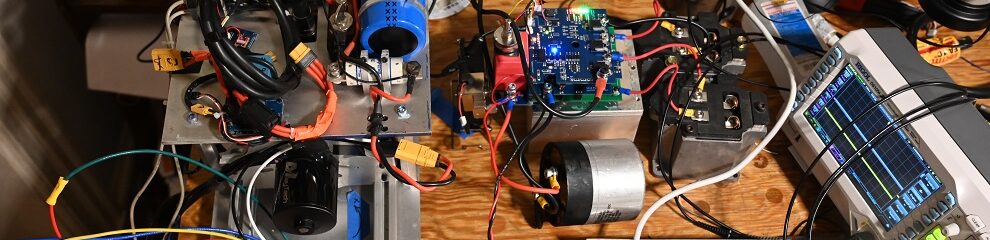
This dyno consists of two rehoused air conditioner motors and the 10 Nm Kistler torque sensor. Mechanically, the dyno consists of a 3/4″ plate of Mic6 I acquired cheaply, with some rubber feet on the bottom. Two 8020 rails allow for any length of motor to be easily mounted. Even better, a 3 jaw chuck allows most inrunners to be easily mounted. For outrunners, the chuck can be removed and the plate behind it has a bunch of different bolt patterns. The torque sensor free-floats between two diaphragm couplings to avoid overconstraint. All of the electronics bolt to a plate on top of this whole thing (not shown) which is mounted on wubs. The electronics on top situation was an interesting move. I figured I’d be reprogramming the inverters and changing wiring a lot more often than I’d be changing out motors, so I wanted easy access to the electronics. This worked out great, although it does make the dyno a bit uglier. Here was the first go at wiring the dyno:

After some wiring cleanup, and a proper photoshoot:

The Details
Electronics
In terms of electronics, there are two identical inverters, both based on STM32G431s and 50A FNB35060T bricks. A STM32F446-based hub board talks to the absorber inverter over isolated CAN and to the test motor over isolated RCPWM (although CAN is supported as well). Both inverters are heat-sunk to the 1/4″ aluminum electronics plate. The torque sensor is read by an ADS1220 ADC, which is a quite a good ADC with an integrated low-drift reference and even a PGA. The ADC is powered by an isoladed DC/DC with a 3-stage RLC network after it, and talks to the hub board over SPI through a digital isolator. A very large 400V 2.7 mF buscap is also mounted to the electronics plate. I added this to keep the bus voltage ripple as low as possible, hopefully improving accuracy of efficiency measurements. It isn’t really clear what happens to efficiency if bus voltage is if it is oscillating wildly, so keeping voltage stable here is in our best interest. The DC bus voltage is divided down by a resistor divider made of 0.05% resistors, and then also fed into an ADS1220. DC bus current is to the test motor is measured by a large 1 milliohm 4-wire shunt, which I measured using a precision milliohm meter to be 0.998 milliohms. The shunt voltage is measured by a third ADS1220, this time with a PGA gain of 16. Both the volt and amp ADCs are also powered by an isolated DC/DC, again with a 3-stage RLC filter after it, and also talk to the hub board over isolated SPI. There are ferrite beads on every wire here to prevent common-mode noise, “the more beads the better.” A 100A semiconductor fuse also is in series with the test motor, hypothetically preventing explosions due to sketchy firmware.
Before the wiring cleanup, I had a ton of trouble with electrical noise. As soon as the bus voltage was increased above 50 volts, 1.7 Nm of bonus torque appeared on the torque sensor for no reason. Tons of noise isn’t really all that surprising, as I’ve got two motors running on high voltage and everything is all bolted to the same aluminum plate. The solution to this was to stick isolated power converters everywhere, as well as ferrite beads wherever they would fit. This solved the noise issues more or less completely, and as I found out made the final measurements extremely clean.
Controls
For the majority of testing, the absorber motor runs in velocity mode and the test motor runs in torque mode. The exception to this is in inertia simulation mode, where they both run in velocity mode, but the absorber velocity setpoint changes as a function of torque. I tuned the absorber velocity loop to be extremely snappy. Additionally, I set up the main hub board to feed-forward the torque sensed at the torque sensor to the absorber motor, which reduces the velocity loop settling time. The velocity loop runs on the absorber motor inverter to minimize propagation delays.
Lets generate an efficiency map!
For data gathering, I run the main loop on the hub board at 500Hz. I set up the ADS1220 ADCs to update at 600Hz, so they just barely finish when the hub board requests new data. The biggest thing which helps make the data here as smooth as possible was the use of moving averages throughout the entire sampling period. Ben also suggested an interesting technique where data is averaged over an integer number of rotations. I did not use this as it matters less the faster you spin. However, I will likely activate this for testing at speeds below 1000 RPM.
For generating this efficiency map, I ran 21 speeds and 31 torques, with a settling time of 300ms and a data collection time of 500ms. I expected this to be nowhere near enough sampling time, but to my complete surprise, the data came out 100% beautiful and smooth on the first try. Complete miracle. I also only turned up the motor to about 50% power, with more power reserved for future work. Peak efficiency was 90.6%±1%. The small jump in efficiency at high speeds occurs as the inverter switches to a different commutation mode at high speeds. I’ve theorized that this would gain a percent or two in efficiency, but I’d never had the tool to verify this. Turns out, it works!

We can also look at the mechanical power, the electrical power, and the power losses. Peak mechanical power is about 1830W. Due to the IPM motor, we get high power all across the RPM band! The white area in the upper right is power attainable only with more volts. The high speed mode simply attempts to do the best it can with the volts available, allowing a small boost in power.

Elec power. Fairly similar to mechanical power.

Power dissipation. More or less completely as expected. It is interesting to note however how power dissipation at high speeds and zero torque is above 100W, most likely due to a combination of windage and resistive losses due to field weakening.

All of this testing was done with a bus voltage of 160V. This test really 100% proves that 160V is nowhere near enough for these motors, as field weakening becomes necessary at only 2500 RPM, which is pitiful. These motors would really cook on 400V.
A Note on Accuracy
The target I set for accuracy on this system was knowing the efficiency of the motor within a percent, so ±0.5% accuracy in the full system. The torque sensor is 0.2% accurate, and it is unlikely that all components will be 0.2% off spec all at once. So, I shot for 0.2% accuracy on each of the four measurements. Three of the measurements are taken by ADS1220 ADCs, which are quite fantastic actually, having a typical gain error of ±0.015% and a integral nonlinearity of only ±6 ppm of the FSR. The reference inside the ADC is even good for ballpark 0.025% accuracy (typical, looking at the graphs). At the moment, the least accurate part of this system is the speed measurement, which is done by differentiating the encoder measurement on the absorber motor every sample period. The resonator on the absorber motor controller is only 0.5% accurate and furthermore the absorber PCB experiences large temperature variations so it is likely to drift. The Kister torque sensor actually has a built in encoder, but for whatever reason it does not work. Eventually I will add a separate encoder just for speed measurement. So, right now I trust the efficiency measurements to ±1%. Really, Ben and I need to dyno some motors and see if we get different results…..
I do know of some people that have access to some high precision voltage and current sources, so these should be pretty easy to calibrate to achieve higher accuracy. Speed is pretty easy, as with a crystal and a good encoder its hard to be wrong. Torque is the hardest to calibrate, but I actually did buy another Himmelstein torque sensor which I will have to use to calibrate this Kistler one.
Buck Converters?
This dyno isn’t terribly useful at the moment for motors other than rehoused automotive air conditioners, because everything really requires 200V to operate. In order to rectify this (no pun intended!), I will need an extremely large buck converter. So far, I have not yet built anything remotely this big, but it is in the works. Stay tuned!
Tips and Tricks
One of the hardest things to figure out on a project like this is which thing will be in command, and therefore what handles the time-critical tasks. For this, the big question was whether to make the F446-based hub board in command, or whether to make some GUI which would handle timing. I chose to make the micro in charge of timing, because micros are inherently good at that sort of thing. When I do eventually make a GUI for this thing, this GUI will probably function much like a slave device where the micro handles requesting for the next data point from the GUI rather then the GUI commanding a sequence of setpoints.
One interesting problem here is that I’m running two identical motors and inverters, which means that one could out-torque the other if commanded to do so. This comes up pretty often, as I continually upload firmwares to the test motor which produce more and more torque. To prevent runaway, I simply capped the test motor to 95% torque, which worked out well enough for testing, and simplified making everything as all the components are the same. If a firmware did indeed produce more torque on the test motor, I just uploaded it to the absorber motor and continued development. The real limiting factor here is the 50A phase current limit on the load motor inverter, so eventually I’ll probably lay out a 75A inverter for the absorber motor.
One of the really cool things about a dyno like this is that it it’s a wonderful display of conservation of power. The test motor takes in electrical power from the DC bus, and converts it to mechanical power on the shaft. The load motor takes mechanical power from the shaft and converts it back to electrical power on the DC bus. So if the system is running at 5 kW mechanical power and both motors are 90% efficient, we will only consume about 1kW from the battery, which is pretty cool!
For this dyno, so far I’ve done all my testing with the dyno powered off a battery. This is a bit annoying because I need to precharge my huge buscap, and also dangerous because there is no current limit. I haven’t really found a good solution other than a battery, because if the dyno unexpectedly regens, it could potentially regen at the full 200V, 50A which is quite a bit of power to put somewhere. The classic solution seems to be a resistor bank, but the resistor bank ends up being about as big as the dyno. As I don’t really have a power supply that can run everything anyways, battery it is for now.
Some more fun photos

