In the previous post, I built and mostly coded the hydro dam boards. But, of course, a system with this many things going on needs to be tested to find the inevitable weird problems.
I had to figure out how to test a hydroelectric dam control system, at home, in my living room, without the rest of the hydroelectric dam. How? Time for a Hardware-In-The-Loop test!
I wanted to test the control system end-to-end, and confirm that everything was working properly and as expected. Here are the things I needed to confirm:
The main controller can correctly read 3-phase voltages and currents, and calculate power correctly
The main controller correctly realizes when something is wrong with the power generation: over and under voltage conditions, loss of a phase, phase power imbalance, underpower or overpower conditions, etc. If one of these errors occurs, the facility properly shuts down.
The main controller correctly sequences the startup and shutdown of the facility, in both normal and emergency conditions.
The main controller and the valve controller talk to each other correctly during normal operation. They also detect communication failure, and shut down correctly.
The valve controller can open and close the valve correctly.
Find any other unexpected behavior.
Let’s start with the power side of the equation. In order to really verify all the grid power measurement and error conditions, I wanted to test with real power actually flowing. Ideally, I wanted to push amps through a motor, and actually generate/measure real electrical power. The issue here is, 80kW is a bit much power to have flowing through my living room. What to do?
The key here is that, in order to test the above conditions, I don’t need to test the full 80kW- I can run just 8 watts, and then scale the power by 10000 in hardware and software. The current sensors on the board are 5A sensors, designed to be used with 40:1 current transformers- so if we just omit the transformers, that’s an easy factor of 40. The voltage sense ADC is also designed to be used with 20:1 transformers, so again, we can just omit the transformers, and operate at way lower power levels. The rest can be made up with software scaling factors. Basically, the goal here is to have the dam controller “have no idea” that its not in the actual dam. Some scaling factors may need to be changed, but the idea is to change as little as possible. That way, when we do get to the actual dam, it should just work.
So, how do we simulate a hydroelectric dam? Firstly, we need to find a way to backdrive the motor, and get it to regen-brake, and generate reverse power. I thought about this way too hard, coming up with weird ideas like mounting a drone propeller to the motor and blowing on it with another prop. Funny enough though, I actually have a device which is pretty good at backdriving motors on command: my dyno! So, all I have to do is mount my motor on the dyno connected to a fake grid, and backdrive it to simulate the motor producing power. OK, sounds like a plan.
First up, we have to make a fake 3-phase AC grid. I don’t have 3-phase power in my house, and 3 phase 208V power is a bit spicy to deal with in preliminary experimental testing. After way too much thinking I realized I could just use a motor controller to generate a 3-phase voltage. Voila! The filters on the board filter the PWM just enough to make it work well enough for testing.
Next up, motor. Ideally, I wanted to have a real 3-phase induction motor, in order to actually test and confirm that the 3-phase code power measurement and error checking code was working. However, small, low voltage induction motors are hard to come by. I tried to use an old stator I had, and I turned a solid aluminum cylinder to be an induction motor rotor.
This ended up working incredibly poorly. I put the motor on the dyno and fed sinusoids of varying frequencies into it. The torque output was: yep, that’s right: 16mNm. Literally barely enough to overcome its own bearing friction. Not at all enough to overcome the friction of the dyno.
So, eventually, I decided that I would do the testing with a brushless DC motor, and that would have to be close enough. I eventually ended up using a brushless motor I had laying around with a 20:1 gearbox on it. This was nice because the motor could spin pretty fast without the dyno going at high speeds.
The control here was a little interesting. I programmed the motor controller to run a speed control loop, but with only proportional gain. So, with a load, the speed would sag below the setpoint, and with backdriving mechanical power input, the speed would increase above the setpoint. This meant that with the bearing friction of the dyno, the motor would do positive work to spin the dyno. But, if I put the dyno in speed mode, and slowly increased the speed, eventually, the motor would begin to get backdriven and produce power instead of consuming it. This took some trial and error to come up with, but ended up working great.
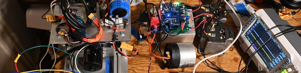
I wired the motor controller and motor such that the dam controller could sense the voltages and currents. Originally this did not work, as with the motor spinning at 60 electrical Hz, the back-EMF was too low. However, I then tried spinning the motor at 300 electrical Hz and it produced enough back-EMF to be read. So, for the majority of the testing, I disabled grid frequency errors. I tested those separately to make sure they worked though, which they did.
Here is a schematic of how the motor and controller were connected to the main hydro dam controller board. I skipped the voltage and current transformers, which made the motor seem like it was much more powerful than it actually was. I also added in some scaling factors in software to get the voltage and current higher.
Also, it is worth noting that the entire above setup took a ton of thinking about/trial and error to get to work- I tired a ton of different motors, control strategies, even building my own motors, to get this all to work. I found many, many ways to not test a hydro dam. But eventually, I found one that worked. Persistence!
Next up: the valve controller. The valve controller took a bit of time to get working. I used the op-amps internal to the STM32G4, and also I had a solder bridge on one of the boards. But, I persevered.
So, what should the valve controller run to simulate fake dam operation? Obviously, a real valve, with some water pressure behind it. Aaron and Alan made me an incredible pipe apparatus. The pipe apparatus fits right in with the incredible disarray of my living room turned hydro dam lab:
Normally, I do not, ever put vertical photos on my blog, but this time it was necessary. This apparatus comes about 4″ from my ceiling. It has a motorized sprinkler valve at the bottom and then a DC pump as well to refill the water column. Given that I am running all this testing in my living room, I decided sadly not to actually fill the water column, although I did make all the wires long enough that if desired, I could put it outside and run the wires onto my porch.
The valve position was read by the same car suspension potentiometer we will be using in the real facility. In order to get the valve to open slowly, like it does in the real facility, I used some 50 ohm resistors in series with the motor. The motor was only a 12V motor anyways, so the resistors were necessary.
So, let’s put it all together. This is best shown in the video. There’s a lot going on here.
Getting this whole setup running took a while, but it was extremely worth it- after seeing this all run flawlessly, I felt confident that the setup really was ready for actually running the real setup. Read on to the next post for facility installation.
Part 2 of the hydro dam project: time to build some new stuff. Rather than attempt to get the dial-up-connected 1985 PLC control system to work, I decided to pursue a lifelong dream to have a nucleo connected to something way bigger than it really should be. A plan began to form. It was time to build a hydroelectric dam controller, nucleo edition.
At a high level, the control system of a dam has two functions. Firstly, the system must be operated correctly and safely, doing things like properly executing startup and shutdown routines, and shutting down if anything goes wrong. Secondly, the system must modulate the turbine to maximize facility output power with the changing water flow. If a nucleo can commutate a motor at 40kHz, if can certainly do this, although we may need the help of a few I/O multiplexers. Let’s get to it.
I laid out two boards, a site controller and a valve controller. The sum of them is by far the most complex EE project I’ve done in terms of number of things going on.
At the heart of the site is the main dam board, which manages the operation of the site. I spent about four months laying out this gigantic board. This board uses nearly every single pin on the nucleo, and in addition uses a total of nine multiplexers as well to get even more I/Os. At 360mm x 240mm, this is, for sure, by far the most large and complex board I have ever layed. The nucleo chosen was the Nucleo-H753, which is the biggest single core nucleo available. I have no idea how to program multiple cores, so single core it is. One core is more than enough for this, given that the core runs at 200MHz and the update rate of my loop here is only 100Hz. I guess a second core could allow for some error checking, but that’s what the valve controller is for. The STM32H753ZI has three ADCs and a ton of analog-capable pins. That was nowhere near enough though, this board has three 4:1 analog multiplexers on it, and the 4-20mA daughter cards all have 3:1 multiplexers as well. The nucleo also has loads of communication peripherals and timers, many of which I am using. The board actually really isn’t complex, but there is a lot going on.
I designed this board in EAGLE as I am faster at eagle than I am in Kicad. I designed this board to be extremely overkill, and have way too many I/Os, for as much future proofing as possible. One interesting topic is the many daughter boards on the board. I was too lazy to figure out how to use the “replicate layout” feature in eagle, so I just made any part I wanted to replicate as a physically separate board, and then I laid out that board as a footprint and put a few on there. This is a good idea for another reason: if any of the I/O modules get blown up, I can replace them as a unit, instead of replacing or having to rework the main board.
I got the SMD components placed by JLCBCB and soldered on the thru-hole parts. This was pretty nice.
This board does A LOT of stuff. Here are all the sections of the board, in roughly left-to-right order:
Top Left: Front Panel light switches. 12 outputs. These are PTC-protected 300mA SSRs. We may use LEDs on the front panel, or we may use the existing 110V bulbs. I didn’t have enough pins here so I used two shift registers. Annoyingly JLCPCB didn’t have these specific shift registers in their inventory, so I reflowed the tiny shift registers on myself.
Center left: front panel button inputs. 16 inputs. I wanted many inputs for future proofing. The I/O cards here have ESD protection diodes and RC filters to prevent static from killing the main board.
Lower left Molex mega-fits: 2X 24V PSU inputs. Dual for redundancy. Additionally, if one PSU dies, we can still safely control the dam, and shut it down. Both PSU inputs have fuses as well as voltage and current sensing.
Bottom left phoenix contact screw terminals: 24V outputs for whatever is needed.
Bottom center-left: non-isolated analog inputs. These were originally intended to go to isolated K-type thermocouple amplifiers, so we could sense the temperature of parts such as the turbine, transformers, etc. However, they can be used for anything really.
Top center-left: the nucleo. STM32H753ZI, the 144 pin behemoth. I could have probably laid this out with the bare chip, but I wanted to be able to replace the nucleo as a unit in case it got ESDed or something. This board also has ethernet if we want to do some serious control of something in the future.
Under the nucleo: dual SD-card data loggers. Upon further thought, two loggers is really not necessary, but the space is there. Maybe I could have once log once a day and another log only when things change.
Under the loggers: Atmospheric pressure and temperature sensors. We need to sense the depth of the pond, and one method of doing this is with water pressure sensors. The pond depth can be calculated by knowing the water pressure. However, the atmospheric pressure must be subtracted from this to get an accurate reading. It is also just good to know. Turns out, after some data logging, we now know that the turbine shack gets to nearly 100 degrees in the summer.
To the right of the loggers: some analog multiplexers. There are a lot of analog sensors on this board.
Top center of board: 2X isolated CAN transceivers for future expansion. Likely, one of these will talk to a VFD in the future.
Center of board: 2X SSD1309 OLED screens. Nice to know what the board is doing. The screens show important data such as grid voltages, currents, output power, main contactor status, valve status, and any fault codes.
Center-right: ESP32 for internet connectivity. At some point we may wish to export data from the dam directly onto the internet, or control the dam through a web interface. This is not currently programmed, but could be done in the future.
Bottom center-right, 4X cards: 12x isolated 24V 4-20mA sensor inputs. This is for 6 depth sensors and 6 future expansion sensors. Each card has a three-way multiplexer on it, which is in series with the other analog multiplexers on the main board- getting all these ADCs to fire right was very tricky for sure.
Bottom right: fiber optic TX and RX for talking to the valve controller. These transmit data over UART to and from the valve controller. The main board transmits a series of bytes in sequence to the valve board, along with the desired valve position. If the main board skips any of this specific sequence for more than a second, the valve controller assumes the main board has gone haywire, and closes the valve.
Right side, up from the fiber: 3X isolated hall-effect current sensors for measuring the generator phase current, through current transformers. These sensors are good for 10A, and the current transformers in the panel are 200:5, so 10A is fine. We plan to run at about 100A which maps to 2.5A on the transducer, but this is RMS, so having a 10A current sensor is about right.
Right side center: 4X contactor outputs. These contactors control the main contactor, the PFC capacitor relay, and a braking contactor for the motor.
Top right: Line voltage ADC. The line is 480V line to line, or 277 line to neutral. Designing a board with 480 (700 peak!!) on it is a bit above my pay grade, and we also did not want 480V wires going into the control side of the cabinet. So, we bought three 480V to 24V transformers and will use these to measure the line voltages. The biggest thing that this has to deal with is surges on the power line, such as if lightning strikes the power line, which is apparently not uncommon. We really do not want a pulse to get in and fry the nucleo. To deal with surges, we have many cascaded layers of protection. Firstly, the any pulse on the 12.7 kV line at the site would have to go through the main transformers. Then, we have the 480V to 24V transformers, which should add a bit more portection. If a pulse gets past this, it has to go through all the board protection. I have a 50mA fuse and a MOV. If the surge stays long enough, it will just blow the fuse as the MOV takes the power. Also, I have a 100k resistor divider, and a further TVS to clamp after the divider. On top of all this, I am using 6000V- rated analog isolators as a further step, so all three phases can float with respect to the rest of the board. So, I think it is very unlikely that a pulse will get through all of this and fry the nucleo.
Lastly, to the left of the contactors: a small buzzer. Beep-beep when there are errors.
I tried to design this board as well as I could for some amount of fault tolerance. Isolation helps a lot, in my experience at least if one side of an opto-isolator gets fried, the other side will be ok, so I used either optos or digital isolators for whatever I could. I was mostly worried about either the grid wires getting struck by lightning (which would put a pulse into the line voltage sensors), or the pond getting struck by lightning (which would put electrons up the depth sensors). The depth sensors are shielded, and we can ground the shield, and I guess the pond is grounded too, but still, I didn’t want to take any chances. One piece of advice I got from a very wise EE man was to put very small inductors in front of ESD protector diodes on all the inputs. If a pulse comes in, it can apparently be fast enough to get through before the ESD diodes turn on. So, the inductors slow down the pulse to where the ESD diodes will catch it. If not an inductor, then I used a big resistor. I used some fuses on the main power and contactor outputs, but if these blow, something is really wrong.
Kudos to the great Nick Sorenson for helping me with a design review.
The only thing that fell through the cracks on this whole board was that the contactor drive relays are driven by DRV103U chips, which switch the low side of the contactor, not the high side. I wired them in on the high side, silly me. I fixed with a quick bit of bodge wire:
I call this very good, one error for a board of this size is truly a miracle.
The second board I laid out was the valve controller. This was a bit more of a 3D board. This thing takes in commands over fiber-transmitted UART from the main board, and opens and closes the valve. This board also functions as the watchdog of the site. It has a 8000V-isolated relay which will be wired in series with the main contactor control drive. If the main dam board goes nuts and stops transmitting data to the valve board, this relay opens, which can shut off the site.
Here is the valve controller board.
This board was laid out in a bit of a rush, and so it didn’t go together quite as well as the others. Noticably, one of the buscaps on the upper left intersected with some of the zener diodes, so I chose not to install it. Too bad. I also hand-assembled these boards, because I was worried about tariffs. The battery fuse also kind of intersects the main board relay, so you have to bend it maybe 0.2mm to get it in.. not too bad. But, surprisingly, no bodge wires needed for this board.
Feature list for this board:
Bottom left: 48V PSU input. This input is fused and has series resistors. The idea here was that a 48V PSU would trickle-charge the battery through the resistors, but I think we’ll just put a CC/CV charger right on the battery, so this input won’t get used.
Right of the 48V PSU input: 48V battery input. As discussed before, the board is mainly powered by the batteries. This enables the valve to close even in the event of a total grid failure, which is critical for the site. This is where the real power comes in to power the board. It has one contactor for precharge and another for power. It also has a 50A fuse.
Right of the 48V batt input: motor phase output. This is just a normal H bridge situation. Low side shunts provide current feedback. The motor consumes about 10-20A, but I wanted overkill, so I put two fets in parallel.
One more right: motor field drive output. The motor is a wound-field motor, so it requires a field drive. This is a low side drive. In my testing the field consumes only about an amp.
Big white relay on the bottom: This is an 8kV rated isolation relay. This is the dead man’s switch for the main contactor. If the valve board stops receiving data over the fiber, it opens this relay.
Bottom right phoenix contact connector: limit switch input. There are big limit switches that sense the valve position. There are two switches per side for redundancy.
Right center of board: optical fiber TX and RX. These transmit data over UART to and from the main board. The main board commands a valve position, and the valve controller transmits the real measured valve position. If the valve controller does not receive a special character sequence every second, it assumes the main board has had a software crash, and it shuts the valve and opens the main contactor.
Top right conntector: Connector for valve position sense potentiometer, and thermal limit switch. The potentiometer senses the valve position. If the thermal limit switch opens, the motor has assumed to be overheated.
The Programming of the setup…..
The programming of the setup was substantial. There is about 2000 lines of C code, not including all the .h files and auto-generated setup garbage.
See if any sensors are out of range, raise error flags if they are
Measure the front panel control buttons and see if we need to chagne the state
Run the state machine depending on front panel buttons and error flags.
Communicate with the valve controller.
Set the main contactor, PFC relay, brake relay, and hydraulic pump control contactors.
Set the front panel lights and the buzzer.
Update the screens.
The ADC setup for measuring the grid is also worth noting. I used ADC1 and ADC2 on the H7 to read the analog sensors, and dedicated ADC3 to only sampling the line voltages and currents. The main loop was run at 100Hz, but this is nowhere near fast enough to sample the voltage and current waveforms. So, ADC3 is setup to trigger off a timer and run at 6kHz. This ADC puts data into a buffer. When the main loop fires, it reads this buffer, and calculates the RMS voltage, peak voltage, RMS current, grid power, and grid frequency.
The Brake Relay
One interesting feature of our site is that we decided to modify the turbine to fix the blade pitch. This is definitely overall good, as its much less maintenance and simpler operation. However, it does leave the possibility for turbine overspeed if the grid suddenly drops. Apparently, it is not that uncommon for someone to drive a truck through a utility pole or something like that, which would likely result in all wires no longer being connected. The water continues to flow and exert torque, but all of a sudden the resistance drops to zero- get ready for exciting failure modes. Ideally, we could just shut off the water instantaneously, but this is not possible for two reasons. First of all, the valve takes about 30 seconds to close just because the motor is slow, and secondly, you wouldn’t even want to close it any faster, because you would get water hammer.
Let’s do some simple math, neglecting viscous losses. I assumed that the induction motor rotor has a rotary inertia of about 1kg*m^2. The turbine has a 5.6:1 speed increaser. If the roughly 2000Nm of torque we expect during operation continues to be applied to the prop, the induction motor rotor will spool up by 3600RPM per second, so in 2.5 seconds the rotor would almost certainly explode when the rotor hits 10k RPM. While there is probably enough oil whipping and water sloshing losses to prevent the motor and propeller from really going nuts, I’d prefer not to find out what the true maximum speed of the turbine really is, and if motor rotor detonation does or does not occur at this speed. So, we must figure out a brake.
For a BLDC motor, this is pretty easy: just place a resistor across any two phases and you have a motor brake. Induction motors are a little different. No back-emf is produced by just spinning the rotor, so instead we have to put some amps across two phases. This will turn the motor into an eddy current brake. So, we plan to have a battery, resistor, and contactor to drive some amps across the two phases of motor. This has yet to be implemented in the actual site.
Some more images of board stuff.
Some great protection on the daughter boards. The 4-20mA daughter boards also have 50mA overcurrent protection ICs.
So, now that we got some hardware in hands and some coding done, it is time to test stuff out. But, how on earth do you test a hydroelectric dam?? Especially when the prospect of motor rotor detonation is real??? Read more in the next post.
What ties together gas engines, buck converters, brushless motors, and steam engines? The ability to convert energy from one form to another potentially more useful form, be it heat to mechanical, electrical to mechanical, or electricity from one voltage to another. I have long been fascinated by energy and power. When one uses a lot of energy in their daily life, it becomes natural to ask, where does it come from? In New England, most energy these days comes from natural gas. But a nonzero, and rising, fraction comes from renewable sources, such as wind, solar, and hydro power. Hydro power has always captured my imagination, where the flow of water from a river is used to do useful mechanical work. There is some beauty in the combination of energy and the flow of water.
Anyways, fast forward to July 2024, and my longtime friend Aaron Sliski found a hydroelectric dam for sale, of all places, on Facebook marketplace. The dam was a roughly 80kW site located in Ashland, NH. Aaron’s father, Alan, also had a longtime interest in hydro power as well, so the three of us stretched our finances to form an LLC and purchase the dam. This project is mostly for fun, but I am betting it will work out financially as well. I think electricity prices will likely double in the next 10 years, given electric cars, heat pumps, hotter summers, AI model training, nuclear power stations closing down, etc. But, we’ll see if those bets work out.
Anyways, we purchased the site, located in beautiful Ashland, NH. Lake-front property!
Some history: the dam was originally built in the 1860s to power a paper mill. It was originally hydromechanical, but was converted to hydroelectric at some point. A major refurbishment happened some time in the 1980s, which is when the current turbine was installed. The turbine unit was manufactured by Hydrolec, a defunct company from Canada. The first thing we heard about this unit was that it was blown up, and that it had a set of variable pitch blades controlled by pressurized hydraulic oil inflating a truck airbag at the front of the unit. This all sounded incredibly bad. It turned out however, that the unit was not too bad overall, and that with a bunch of rust remover and an added thrust bearing, things went together alright. We ended up getting the old turbine patched up well enough and got it installed in the facility. Aaron’s blog covers this in pretty good detail. I’ll focus this blog on my electronics, which was my contribution to the project.
Here is the dam and turbine building. So beautiful!
The dam was officially purchased at the end of the summer. The next step was deciding a division on labor: Aaron became the mechanical guy, and Alan became the paperwork guy, and I became the electronics guy.
Some more detail on the site…
In terms of hydraulic capacity, the site runs about 60-100CFS (cubic feet per second) and has 18ft of head, if all the flash boards are installed. At 80 CFS, with an efficiency of 60%, we predict an output power of 73kW. Apparently we found an old manual which says the turbine is 60% efficient. The flow does sometimes surge to several hundred CFS, but that is rare.
Power-wise, the site has three 37.5kW pole pigs, which step down the 12 kV line to 480V. So, the total export capacity is 112.5kW. The 480V is a delta connection, so this is line-to-line voltages, and there is no neutral coming to the site. The site additionally has 120/240V single phase service to power the building. I guess at some point these could be combined, but it is nice to have them separate for now.
Somehow, the site also has three meters attached to the 480. Why? Unknown….
Here is the business end of the facility. The penstock is a 52.5″ diameter steel tube which tapers down to a 3′ turbine section. The turbine is mounted at a 45 degree angle sticking out of the wall of the turbine house.
A gigantic butterfly valve inside the penstock controls water to the facility. This valve is electrically operated with a 48V wound-field motor. A bunch of car batteries in series provide power to run the motor. The batteries are important: if the facility suddenly loses all grid power, the valve must close to shut off the water. Therefore, the batteries are mandatory to provide power in this situation. It is also worth mentioning that the valve cannot close very fast. It takes about 30 seconds for the valve to go from fully open to fully closed. Furthermore, it is actually desirable to close this valve slowly, otherwise you will get water hammer.
Here is the turbine. We think the whole turbine unit weighs probably 8000 lbs. Here, Aaron is shown using a brass rod as a gong to hammer the propeller onto the motor unit. The bearings didn’t like it probably, but hey, it worked and the bearings were fine.
It is also worth noting the way the turbine is controlled. Hydro sites have to generate power with a variable flow, and there are many ways of accomplishing this. The original method was that the unit was filled with pressurized oil, which inflated a truck airbag spinning on the front of the prop, which was connected to a series of linkages which altered the propeller pitch. We originally thought that this was a complete trash system. However, upon further thought, my opinion has changed. Given the technology of the time this turbine was built, this isn’t a bad system, given that there are no weird thrust bearings and most moving parts are submerged in the oil instead of the water, preventing rust. However, in 2025, we have the magic of VFDs, so we can just vary the motor speed. Maybe some marginal efficiency could be gained by varying the prop pitch, but it probably isn’t worth it. We almost considered getting this system going again, but Aaron found we were missing the “Jesus bolt”, so we proceeded with fixed pitch.
The fixed pitch does create one critical problem though. If the grid is instantaneously disconnected, the turbine has no load, and it is still is producing substantial torque. In the original pressurized oil system, the pressure could just be popped to flatten the blade pitch very quickly. However, with the fixed pitch, this is no longer possible. Neglecting fluidic losses, I calculated that if the grid drops and the water continues to flow, the induction motor rotor would likely spool up to detonation speed in about a second. The valve takes about 30 seconds to close, which is too long. It is likely that fluidic resistance is substantial, which will help to prevent overspeed, but we have to plan for the worst case scenario. More on this later- we need to figure out a way to turn the motor into a brake.
The turbine motor is a gigantic 3-phase induction motor. This thing is immersed in oil, which is then under water, so you could say it has good cooling. The motor apparently weighs about 1200lbs.
Let’s get to work…..
My first task was to look over the existing electronics cabinet. It was all installed in the 1980s, and controlled by a PLC with a dial-up phone connection. All components made well before I was born.
The dam control system has two major functions: Firstly, to turn on the generator properly and shut it down if anything goes off-nominal, and secondly, to servo the power level to extract maximum power for a given amount of water flow. The existing control system was apparently not too bad early in life, however we heard that in latter years things went downhill, with either substantial water going over the dam or the stream running dry. It also came with zero manual, so even if we did want to get it going again, that was a tall ask.
A plan began to form. I’ve always thought it would be fun to have a nucleo control something big. So, a plan was hatched.