The successor to the small dyno: the big dyno. This dyno should be good for around 30 Nm continuous up to 8-10K RPM, and then around 20-30kW from there. It is a lot of dyno.. should be excellent. This size of dyno was inspired by Ben and Bayley’s big dyno. Finding myself in need of a more powerful dyno to test ever larger motors, it was time to build my own.
Here is the CAD as it stands.

The dyno is largely based around an altermotter paired with an HBM 100Nm 20,000 RPM digital output torque sensor. Interestingly enough, the torque sensor has no bearings. As far as I can tell, the housing is supposed to be supported by the dyno frame, and not actually touch the shaft at all. Low drag I guess…

The frame for the dyno is made out of 40mm 80-20 extrusion. Torsion is resisted by two 1/16in aluminum sheets, which I had lying around. I simulated this in FEA, and found the deflection at the load motor shaft to be on the order of half a mm. Tubes are stiff! Should make a nice lightweight frame, although low-mass isn’t really a big concern for something like this. For load motor mounting, I used the same strategy that my small dyno has: two slide-able 8020 rails, to which I’ll likely mount the same cross-piece with optional 3-Jaw chuck. This worked extremely well on the small dyno and was hilarious. This is not in CAD yet. All of the electronics are mounted to a large water block, which will be in the same cooling loop as the absorber motor. One big difference for this dyno is that it will have a buck converter in the middle, as opposed to the small dyno directly ran off a battery. The buck-style dyno is harder to execute, but allows greater flexibility in testing. Additionally, it becomes extremely easy to test brushed motors, although I won’t do this often. The small dyno does not currently have any way to test low-voltage motor systems, so having this capability on the big dyno will be very useful.
The biggest decision on this dyno was the electrical layout. The original scheme was to have two batteries, one for each side. This is nice and very reliable, because the batteries prevent any fast over-voltage transients. The addition of a buck converter prevents needing to stop the test to discharge the absorber battery periodically. In this scheme, the buck converter can be half as big because it only has to to take the average power, not the continuous power.

However, this isn’t great- managing one or even two 400V batteries is no joke. Dealing with precharge circuits (or lack thereof) on the small dyno was extremely annoying, and at the moment I don’t even have a 400V battery anyways. One final problem is it’s not entirely clear how to run the buck converter- should it be constant-current? Or, if constant voltage, which voltage- the input or the output? Eventually, I decided to make the jump to a single battery dyno, increasing the size of the buck to a 200A buck to be able to take the full load and not just transients. In order to keep the transients to a minimum, I increased the size of the absorber side bus caps. I may also add an emergency braking resistor, just in case of buck converter failure, but that is reserved for future work.

Onto the subject of today….
Surprisingly, I have almost all of the big electrical components I will need to build the dyno- I have a fairly large stash of big inverter parts from some startup cleanout, I have a bunch of Prius inductors from MITERS, some allegro current sensors from old projects, even some cool SiC bricks my work was tossing out, some big 225A fuses from Battlebots, and even some big water blocks. The only large component I found myself needing was the massive absorber-side high voltage buscap. I unfortunately find myself needing about 2-5 mF at 400V, a whopping 300 joules of cap (definitely in fuse-mandatory territory). The worst-case scenario here is if buck converter is running full amps backwards (boosting, testing regen on the test motor) and the absorber motor suddenly stops drawing current. In this scenario, the buscap will be charging at 200A, and the buck/booster has to shut down before it blows up anything. Additionally, even if it stops at that same instant, the energy stored in the boost inductor will end up in the high voltage bus cap as well, although this is only about 5 J. I’ll probably be running the booster at 50kHz, so the outer voltage loop will have a crossover somewhere around 5kHz. Therefore, the reaction time of the booster will be about 0.2-0.5ms. At 200A, a 1 mF cap charges at a rate of 200 V/ms, so the situation is actually fairly critical. With a 5mF buscap and a reaction time of 0.5 ms, this is cut down to only an overshoot of 20V, which is more manageable.
As the largest film cap in my collection is only 420uF, I began to experiment with other options. Electrolytics are notorious for significantly higher ESR than the film caps I am used to, but it does seem that the industry-accepted solution for this problem is just to use a lot of them. I found a few VFDs a few months back at the Stata loading docks, with the usual forest of electrolytic inside. As these caps are indeed the total energy for what I need, I decided to investigate further. Electrolytics are strange- looking up the datasheet for these caps, they are rated for a pitiful 2.5 amps of ripple current. Huh? However, the VFD in question was a 100A VFD, so these caps would see about 6.5 amps at full load in the VFD, with zero cooling. In my application, they would see 25 amps per, which is a considerable uprating. I decided the only way to proceed was to actually test whether these could take the ripple I desired.

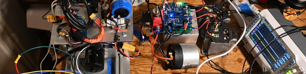
After a bunch of putzing around, I eventually found the easiest solution to run this test was to put a power resistor inline, and then just to drive a square wave across the cap. I adjusted the resistor until I got the ripple up to about 22 amps, which is close enough.

To my surprise, this cap actually dealt with the ripple with no problems at all. After running for about 20 minutes with no fan, the cap barely got warm. Pretty cool!!! I don’t think I’ll end up actually using these caps as it is annoying to package so many of them, and they are only rated for 385V and not the full 400V. I found some other caps in the slums of MITERS which I think should do the trick. An experiment in Capacitance: Ripple on Electrolytics!
Here is a quick scope shot of the ripple test. The voltage swings about 7.5V in 250 uS. On a 740uF cap, This equates to an average of 22.2A of ripple. The cap barely got warm. Not bad!

Stay tuned, I just placed a big board order, and the 8020 should be arriving soon. Should start coming together soon…


