In the previous post, I built and mostly coded the hydro dam boards. But, of course, a system with this many things going on needs to be tested to find the inevitable weird problems.
I had to figure out how to test a hydroelectric dam control system, at home, in my living room, without the rest of the hydroelectric dam. How? Time for a Hardware-In-The-Loop test!
I wanted to test the control system end-to-end, and confirm that everything was working properly and as expected. Here are the things I needed to confirm:
- The main controller can correctly read 3-phase voltages and currents, and calculate power correctly
- The main controller correctly realizes when something is wrong with the power generation: over and under voltage conditions, loss of a phase, phase power imbalance, underpower or overpower conditions, etc. If one of these errors occurs, the facility properly shuts down.
- The main controller correctly sequences the startup and shutdown of the facility, in both normal and emergency conditions.
- The main controller and the valve controller talk to each other correctly during normal operation. They also detect communication failure, and shut down correctly.
- The valve controller can open and close the valve correctly.
- Find any other unexpected behavior.
Let’s start with the power side of the equation. In order to really verify all the grid power measurement and error conditions, I wanted to test with real power actually flowing. Ideally, I wanted to push amps through a motor, and actually generate/measure real electrical power. The issue here is, 80kW is a bit much power to have flowing through my living room. What to do?
The key here is that, in order to test the above conditions, I don’t need to test the full 80kW- I can run just 8 watts, and then scale the power by 10000 in hardware and software. The current sensors on the board are 5A sensors, designed to be used with 40:1 current transformers- so if we just omit the transformers, that’s an easy factor of 40. The voltage sense ADC is also designed to be used with 20:1 transformers, so again, we can just omit the transformers, and operate at way lower power levels. The rest can be made up with software scaling factors. Basically, the goal here is to have the dam controller “have no idea” that its not in the actual dam. Some scaling factors may need to be changed, but the idea is to change as little as possible. That way, when we do get to the actual dam, it should just work.
So, how do we simulate a hydroelectric dam? Firstly, we need to find a way to backdrive the motor, and get it to regen-brake, and generate reverse power. I thought about this way too hard, coming up with weird ideas like mounting a drone propeller to the motor and blowing on it with another prop. Funny enough though, I actually have a device which is pretty good at backdriving motors on command: my dyno! So, all I have to do is mount my motor on the dyno connected to a fake grid, and backdrive it to simulate the motor producing power. OK, sounds like a plan.
First up, we have to make a fake 3-phase AC grid. I don’t have 3-phase power in my house, and 3 phase 208V power is a bit spicy to deal with in preliminary experimental testing. After way too much thinking I realized I could just use a motor controller to generate a 3-phase voltage. Voila! The filters on the board filter the PWM just enough to make it work well enough for testing.
Next up, motor. Ideally, I wanted to have a real 3-phase induction motor, in order to actually test and confirm that the 3-phase code power measurement and error checking code was working. However, small, low voltage induction motors are hard to come by. I tried to use an old stator I had, and I turned a solid aluminum cylinder to be an induction motor rotor.

This ended up working incredibly poorly. I put the motor on the dyno and fed sinusoids of varying frequencies into it. The torque output was: yep, that’s right: 16mNm. Literally barely enough to overcome its own bearing friction. Not at all enough to overcome the friction of the dyno.

So, eventually, I decided that I would do the testing with a brushless DC motor, and that would have to be close enough. I eventually ended up using a brushless motor I had laying around with a 20:1 gearbox on it. This was nice because the motor could spin pretty fast without the dyno going at high speeds.

The control here was a little interesting. I programmed the motor controller to run a speed control loop, but with only proportional gain. So, with a load, the speed would sag below the setpoint, and with backdriving mechanical power input, the speed would increase above the setpoint. This meant that with the bearing friction of the dyno, the motor would do positive work to spin the dyno. But, if I put the dyno in speed mode, and slowly increased the speed, eventually, the motor would begin to get backdriven and produce power instead of consuming it. This took some trial and error to come up with, but ended up working great.
I wired the motor controller and motor such that the dam controller could sense the voltages and currents. Originally this did not work, as with the motor spinning at 60 electrical Hz, the back-EMF was too low. However, I then tried spinning the motor at 300 electrical Hz and it produced enough back-EMF to be read. So, for the majority of the testing, I disabled grid frequency errors. I tested those separately to make sure they worked though, which they did.
Here is a schematic of how the motor and controller were connected to the main hydro dam controller board. I skipped the voltage and current transformers, which made the motor seem like it was much more powerful than it actually was. I also added in some scaling factors in software to get the voltage and current higher.

Also, it is worth noting that the entire above setup took a ton of thinking about/trial and error to get to work- I tired a ton of different motors, control strategies, even building my own motors, to get this all to work. I found many, many ways to not test a hydro dam. But eventually, I found one that worked. Persistence!
Next up: the valve controller. The valve controller took a bit of time to get working. I used the op-amps internal to the STM32G4, and also I had a solder bridge on one of the boards. But, I persevered.

So, what should the valve controller run to simulate fake dam operation? Obviously, a real valve, with some water pressure behind it. Aaron and Alan made me an incredible pipe apparatus. The pipe apparatus fits right in with the incredible disarray of my living room turned hydro dam lab:

Normally, I do not, ever put vertical photos on my blog, but this time it was necessary. This apparatus comes about 4″ from my ceiling. It has a motorized sprinkler valve at the bottom and then a DC pump as well to refill the water column. Given that I am running all this testing in my living room, I decided sadly not to actually fill the water column, although I did make all the wires long enough that if desired, I could put it outside and run the wires onto my porch.
The valve position was read by the same car suspension potentiometer we will be using in the real facility. In order to get the valve to open slowly, like it does in the real facility, I used some 50 ohm resistors in series with the motor. The motor was only a 12V motor anyways, so the resistors were necessary.

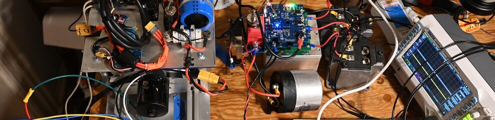
So, let’s put it all together. This is best shown in the video. There’s a lot going on here.
Getting this whole setup running took a while, but it was extremely worth it- after seeing this all run flawlessly, I felt confident that the setup really was ready for actually running the real setup. Read on to the next post for facility installation.