Several years ago, I collected eight free solar panels. These panels are about 21″ square, slightly flexible, and supposedly 50W at 20V. After about five years of tripping on them, I decided it was finally time to do something and put them up. In other news, progress on the hydro dam has been proceeding at a speed roughly comparable to the famous pitch drop experiment, so I have to get my “free energy fix” from some other source. Time to start yet another project…..
So, I got the panels, now all I need to build my solar system is a $300 MPPT tracker, a $500 battery, a $200 solar inverter, etc. It’s so easy these days to do literally any project by just buying several hundred dollars worth of questionable electronics off Ebay, and cobble something together.
But wait a sec- is that really in the spirit of this project? Not only will the payoff time be many years (or maybe even decades), but, more importantly, where’s the fun in that?? What ever happened to actually building stuff?
Back in the days of MITERS, all of us did loads of projects at lightning speed. The MITERS method was use what you have, to get whatever you wanted done. MITERS had such a gigantic load of stuff, so this was easy to do. No browsing through the interwebz, no waiting for shipping, etc. No consumerism. There is something very satisfying about doing a project using only the tools and materials you already have available. These days, after years of collecting, my house is getting full, and so now this is possible to do at home as well. The gold standard is to do a whole project for $0, using only what you have. This is not always possible, but it is an ideal to strive for.
When I started this project, I didn’t really have any idea where the project would go, the idea was simply “do something with the panels and see how it goes, hopefully offset some electric bill.” At 42c/kWh where I live, it does not take a lot of watts to make a meaningful reduction in my electric bill. So, let’s get started.
Here is a rough schematic of the system:

It is pretty simple. At the center of the system is a controller with two half bridges. The half bridge on the panel side acts as a boost converter to charge the battery, and then half bridge on the load side acts as a buck converter to power the load at a steady voltage. The controller charges the battery during the day, and then dumps the energy into the load as required.
Step One was selecting a master controller from my giant pile of old project PCBs. I selected one which seemed to fit my needs well. This PCB had a 2.42″ screen, two half bridges as required (one with current sense), an RTC battery, 4X thermocouple inputs, and a few other GPIO ins and outs. The only real issue with this PCB was that it had an STM32F051 microcontroller, which lacks a floating point unit. No floating point is a pain, so the first step here was a micro swap. Luckily, the F0 and the F3 series are 98% pin compatible, and the two power pins needed for the F3 went to functions not needed for the boards new functions. Some bodge wires were installed and off we went. I made the half bridges switch and the current sensors read.

Step Two was the PWM filters. Firstly, the inductors. The inductors are always the pain point. The inductors have to see full current plus whatever current ripple, and generate losses through resistive, eddy current, and hysteresis losses. You can always reduce these losses by just making the inductors huge, which is what I opted to do. Plus, I had some absolutely massive inductors lying around anyways, so let’s put them to use. These inductors I’m sure were originally good for probably 100A continuous. They accomplished this with probably 20 turns of 5 parallel strands of square wire. I disassembled the crimps on the ends and re-terminated the wiring, so that the 5 parallel strands became 5 series strands. This boosts the inductance by a factor of 25, reducing current ripple by a factor of 25. So that’s good. I measured the inductance at 2.4mH, and checked for saturation, which did not occur at 10A. Good enough. I never measured the DC resistance of these inductors but they are huge so its negligible.
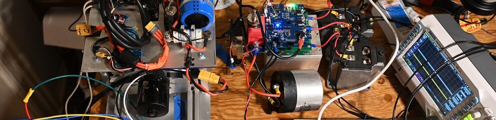
The board hooked up to the inductors. Note the series-izing wiring on the inductors.

Next up was the capacitors. I forgot to take pictures of this but I used 35V 10mF caps for the main capacitors and two 10mF caps in parallel for the damping legs. I tested the ring on this system and the overshoot is negligible, maybe 10%, which is exactly as desired. Great! I forgot to take pictures of the benchtop cap setup but you will see them later on.
With the PWM filters existing and wired up it was time to try actually harvesting some power. Here was the first attempt. I had tested these panels with loading resistors before and found their max power to be about to 25W apiece in full sun. In this test, I tied seven panels in parallel and placed them in my back yard, and expected about 150-200W. To my surprise I got only about 35W. After some voltage measuring, I found the culprit was the ESR of the connection wire, which was a 16AWG extension cord. This is surprising at the time but I guess I should have expected it. I put some much fatter wires in parallel with my original cord and the power came up to about 100W. Still not as much as I was hoping for, but significant improvement.

The proper way to do this is to have the MPPT tracker much closer to the panel, or to put the panels in series instead of parallel. Putting the MPPT controller remotely is annoying because it makes updating the firmware a pain, and putting the panels in series is not an option with my panel/battery combo. So, I just accepted that I would need to use a fat wire to get the ESR down to manageable levels.
Next step was building a roof-mounted panel array, and ratchet strapping it to the chimney. I strapped the panels to the chimney because there are some tall trees very close to the house, and so much of the roof itself doesn’t get sun, especially in winter. My chimney array consists of four panels, so I should get about 100W. I arranged the panels to point towards the morning sun, the thought being that it’s less cloudy and hazy in the morning, so I should get more power. The chimney strapping is a big dodgy. I think the primary concern is wind loading, but due to the small area of the panels, it’s more or less just OK. I looked it up and calculated the worst case hurricane would be about 50lbs of additional side load on the chimney. The top 2 feet of the chimney probably weigh 300lbs alone, so I’m not worried about it.
In building the roof array was, so far, the only time I actually spent money on this project. I bought $8 of wood screws, which I used to hold the panels to the wooden frames. I considered having good screws to be a worthy investment in this project.
Some amount of roof climbing was required to install the panels. The recently acquired climbing gear was used for additional safety. I’d describe this climb as probably a 5.3, with some hard mantle moves required to get over various “roofs,” no pun intended.

The panels installed.

I found that with this cable and these four panels in maximum full no-haze morning sun, my peak power is about 115W. Pretty good!
One minor issue was running the roughly 50′ cable down from the roof. I did not have a suitable heavy gauge cable “in stock,” but I did have a decent pile of 3 conductor 12 gauge wire in 8-10′ sections. I figured this was a good time to use them. I soldered all the spare sections together to make a roughly 50′ cable, which was the perfect length. I soldered the positive and negative wires of this cable to some copper sheet strips, which I then closed a window upon. This worked great for getting the electricity inside.
I made a nice board thing and clamped it into my parts shelf. Dane donated a pair of ~13V, ~30Ah batts which I put in series to get about 700 watt-hours of storage capacity. Thank you Dane!! Here is the hardware unit made all nice, with 3D printed mounts and screwed to a board. I mounted this unit, along with the heavy batteries, to the top shelf on my parts shelf.

Next up was getting the code running well. The majority of this was the MPPT algorithm, which I had thought of a while back but never tried in hardware. Here’s the meat of the code:
Every Loop:
	int run_mppt = 0;

	sine_phase +=6.28318f*MPPT_FREQ/F_SW;
	if (sine_phase > 6.28318f) { sine_phase = 0.0f; run_mppt = 1; }

	float sin_sig = sinf(sine_phase);

	dtc_a = dtc_base + sin_sig*SINE_AMPLITUDE;

	mppt_integral += phA_pwr/F_SW*sin_sig;

	int sign = 1; // change if it doesn't work

	if ( run_mppt ) {
		if (mppt_integral > 0.0f) {dtc_base += sign*STEP_SIZE;}
		else {dtc_base -= sign*STEP_SIZE;}
		mppt_integral = 0;
		solar_pwr_filt = phA_pwr;
	}
Here is the gist of how this code works. First, a sinusoidal signal is generated. The duty cycle of the bridge is some base duty cycle (say, 50%) plus the sinusoidal signal multiplied by some scalar (in my case 2%). So, the duty cycle varies sinusoidally between 48% and 52%. The power generated is then multiplied by the base sinusoidal signal, and that product is integrated over the sine cycle. At the end of this sinusoidal cycle, the integral is evaluated. If the integral is positive, the base duty cycle is increased. If the integral is negative, the base duty cycle is decreased. The cycle then repeats, in my case at about 2Hz. This seems to track the maximum power pretty well. Is this the best way to do it? Who knows, but experimentally it seems to work.
So, once I got this whole thing set up, I waited a day, and, to my surprise, the batteries were fully charged. Who would have thought!
As dumb as it sounds, self-charging batteries is sort of a weird foreign concept to me. As a power engineer, the game is always to spare every precious joule, to extend vehicle range or reduce electricity costs. Never before have I run into a situation where I have too much power, and now needed to find something to do with it. So, the next step was finding some loads to power.
My house always smelled a little musty, and I’ve always been too cheap to just have 24/7 fans running. But now, with free (albeit limited) power, in was time to install some fans. Each fan is rated for 22W at 12V, but I have buck converters reducing the voltage to only about 5V. This is mostly because I want them to be very quiet, and they still move decent airflow even at these low RPMs. Together, these fans consume only about 5 watts of power at this voltage.

The original plan was to have the fans throttle based on inside and outside temperature, keeping the house cooler in the summer and warmer in the winter, which would have been pretty “cool,” heh. This plan never really came to fruition and I have them running at a fixed speed for now. When it was hotter I turned them up a lot more, and this kept air flowing through the house. The real benefit here was probably not the offset of the energy, but reducing the dependence on using my A/C unit, which I managed to use on only one or two extra hot days. I also installed another pair of fans in the bedroom, blowing air in, and I find this improves the quality of my sleep, and again reduces my dependence on A/C. At current speed settings, the bedroom and living room fans together draw about 15W. This is 360Wh/day. If I use the fans at 50% duty cycle (probably off in the winter), this is $28 of electricity per year, at current electricity prices. Not bad!
Next up was powering my overhead light. I got this light off the loading dock about 5 years ago, slapped it on the ceiling, and never looked back. Converting it to solar power was pretty easy, I found that it ran quite happily at 19V DC, so that’s what I supplied it. It consumes 11W at this voltage. I also hooked up a floor-standing lamp, which draws about 30W. If both of these are used for 5 hours a day, this is 205Wh/day.

Next up was my computer monitor. I have a nice 34″ curved LG monitor. The AC adapter supplies 19V. With a deep breath I cut the cord of the perfectly good AC adapter, and hooked it up to a DC power supply. This was no problem. However, in the process of doing this, I made a surprising discovery here- even with everything off, the monitor drew about 10W steady state. Huh?? Where is all that power going?? Who knows. That’s $37 of electricity per year. Bad! So, I installed a relay that closed only when the computer was actually on, preventing parasitic power draw. The monitor was then connected to the solar system, and worked without a hitch. When on, this monitor consumes about 20W. Shown below is my computer monitor setup. The left monitor takes 110 AC in directly, so that was not an option for solar power. Reserved for future work.

Here is the relay that shuts off power to the monitor when the computer is off. Its just a 12V relay hooked up to a hard drive power connector in the computer. If my monitor is off 20 hours per day, this saves $30 of electricity per year.

I tried powering my speakers off of solar as well. This did not work- the amplifier I had started making weird digital noises. I believe this was due to a ground loop created by powering my monitor and the speakers both by solar. I switched the speakers back to AC power. I also did measure the power draw on the speakers while running, and found it to be only a few watts even at floor-vibrating levels. So, this will stay AC-powered for the foreseeable future.
Anyways, that’s the setup. The solar is currently powering two lamps, my computer monitor, and some fans that circulate the air in my house. The system so far has averaged 380Wh/day of generation and usage. Generation exceeds usage so the batteries are always full, only once after three cloudy days did I run out of power. The generation could likely be more, however, my loads don’t draw enough to discharge the batteries and so the panels just charge the batteries and then stop when the batts are full.
I did toy a bit with making an inverter to power the fridge. In the end I decided this wasn’t worth it, it would be cool, but I just don’t have enough surplus power to really power any more loads reliably. Maybe I will install more panels in the future, and then it will be worth it. Also in the future I will probably put a few more things on the solar bus, like battery charging and maybe phone charging, but we’ll see. For now, I am going to consider this project done enough- back to other fun projects.
In terms of dollars, the only dollars I spent were the $8 of wood screws to hold the panels onto my frame. In terms of generation, the system has been on for a bit over a month, but I have been gone for some weeks and I’ve unplugged the system when I’m gone. So far I have generated 11.1kWh, or roughly $4.66 in electricity. So, I am a bit over halfway towards paying off my wood screws. The hydro dam generates 60kW, so this energy could be generated in 11 minutes- crazy how much power a dam makes. Average generation per day has been 0.38kWh. The maximum I’ve gotten in one day is 0.67kWh. I’m not sure how much electricity I will offset over the course of the year given that I will get less sun in the winter, but probably about $50-$80 worth. So, like, not much, but still, the cool factor is pretty high. Maybe I should put up some more panels, but that is reserved for future work. In terms of time invested, I’m sure I would have been better off working at McDonalds, but that’s not the point, I had fun and now I have a cool home solar system 🙂
Stay tuned for future projects!